Page 22: SV Suspension
November 07


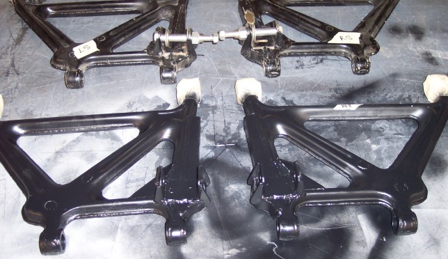
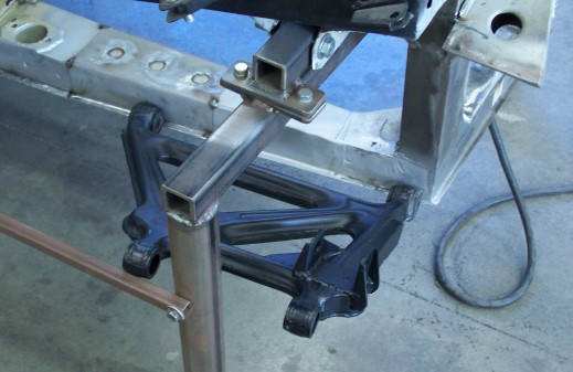
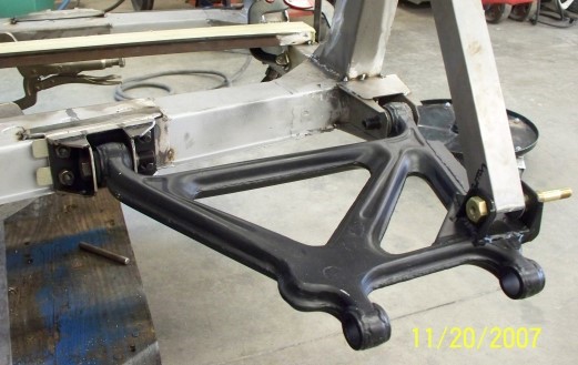
Beautiful, aren't they? The conversion consisted of removing some mounting studs, relocating the brackets (which have the bolts through them on the original SV arms), and adding some stiffeners around and between the bracket posts. (I'll find some photos of unaltered Espada arms for comparison.)
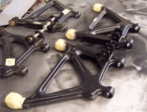
The converted arms are identical to the SV arms. This is very exciting progress. Now that Nigel has finished these, he can complete the mounting points on the frame. Then there are some details on the frame to go over, to make sure all of the S and SV upgrades are complete. Then on to the body work!
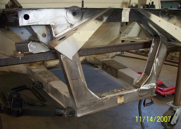
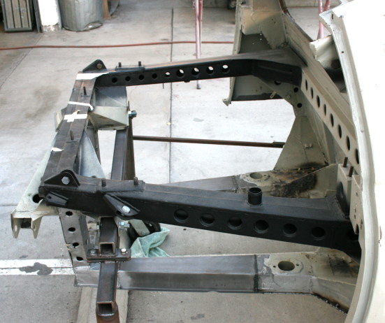 | Here is the rear frame with the lower P400/S suspension points removed; just clean metal. Notice the four holes in the rear upright. And recall the crack at the top of page 4. Although the holes reduced weight, the uprights could crack, so there were no holes on the SV. |
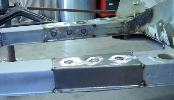 | To mount the SV suspension points, the frame is capped with heavier metal. Holes in the mounting plates provide more places to weld them to the frame. Another, even thicker plate will be welded on to this - in just the right place - with four bolts protruding. The suspension bracket will be bolted to the frame. This allows for shims to be placed between the plate and bracket to adjust toe-in. |
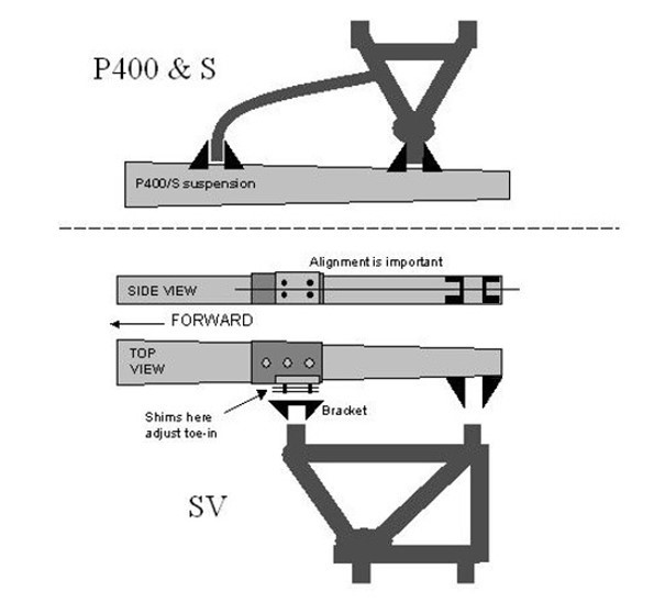 | The top drawing shows the P400/S suspension with the inverted A-arm and trailing link. For the SV, in the lower drawings, a bracket (not in the photos) will be bolted to the frame. Shims between the bracket and the frame adjust for toe-in and the angle at which the bracket is mounted (there can be different thickness on any of the four bolts, as needed). Shims can't adjust the center line in the SV side view, so the position of the bolts is important. And of course all four holes through both brackets must line up. |
 | And here is about where the new A arms (H arms?) will go. Notice that the holes in the upright are gone - replaced with new metal! |
 | Here's another shot of the rear of the frame, showing that the uprights are now solid. These won't crack! |
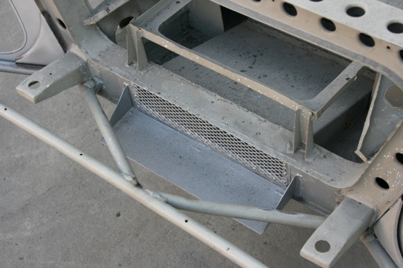 | Some work has been done on the front too. The vent opening has been covered with a screen and a small scoop has been added. These are S modifications. Most of the dirt on the frame is soot from the horrible San Diego wildfires. |
 | All the mounting points are now tacked in position so that final measurements can be taken before they are fully welded in place. The square tube is where the shock absorber will mount. |
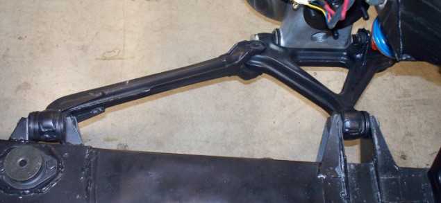 | Here is the suspension for a P400 or S for comparison. |